IQ Imbalance Compensation in OFDM Systems #
This code covers: Correcting IQ imbalances in OFDM systems.
Papers #
Results From Code Below #
Code #
IQ_imbalance_dB = 10;
%parameters for sim
%carrier frequency offset
BW = 1e7;
cfo = 0/BW;
%noise amp
n_amp =eps;
%phase offset
cpo = 0;
%channel
chan = 1;
%fft length
N=64;
%cyclic prefix length
cycPre = 16;
%CREATE RANDOM QPSK DATA TO SEND
qpsk1 = (floor(2*rand(1,26))-.5)/.5 + 1j*(floor(2*rand(1,26))-.5)/.5;
qpsk2 = (floor(2*rand(1,26))-.5)/.5 + 1j*(floor(2*rand(1,26))-.5)/.5;
inputiFFT = [zeros(1,6), qpsk1, 0, qpsk2, zeros(1,5)];
outputiFFT = ifft((inputiFFT),N);
outputiFFT_with_CP = [outputiFFT(49:64) outputiFFT]; %CYCLIC PREFIX
%construct the signal around some noise (640 samples noise SIGNAL 320 samples noise)
tx = 20*[outputiFFT_with_CP];
txall = [tx] ;
%pass through channel add noise
noise =n_amp*(randn(1,length(txall))+1j*randn(1,length(txall)));
IQ = filter(chan,1,txall) + noise;
nn = [0:length(IQ)-1];
w = 2*pi*cfo;
ejwn = exp(1i*(w*nn + cpo));
%apply cfo to the signal
IQb4 = (IQ/20).*ejwn;
%APPLY IQ IMBALANCE
IQafter = iqimbal(IQb4,10);
IQ0 = IQafter;
ghat = sqrt( sum(imag(IQ0).^2) / ( sum(real(IQ0).^2 )) );
theta = sum( real(IQ0) .* imag(IQ0) )/ ( sqrt(sum(real(IQ0).^2)) * sqrt(sum(imag(IQ0).^2)) );
thetaH = -asin(theta);
img = ( imag(IQafter) + ghat*sin(thetaH)*real(IQafter))/(ghat*cos(thetaH));
IQcor = real(IQafter) + 1i*img;
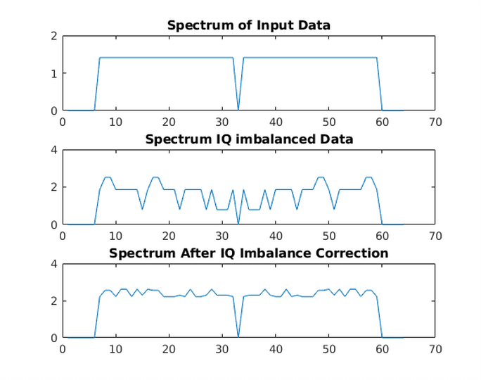
figure
subplot(311)
plot(abs(fft(IQb4(17:end),64)))
title('Spectrum of Input Data')
subplot(312)
plot(abs(fft(IQafter(17:end),64)))
title('Spectrum IQ imbalanced Data')
subplot(313)
plot(abs(fft(IQcor(17:end),64)))
title('Spectrum After IQ Imbalance Correction')