Carrier Frequencty Offset Correction in OFDM Systems #
This code covers: Carrier frequencty offset correction in an OFDM system
Orthogonal Frequency Division Multiplexing (OFDM) has become a widely used modulation scheme in modern communication systems, thanks to its ability to combat frequency-selective fading and provide high spectral efficiency. However, one significant challenge in OFDM systems is the presence of Carrier Frequency Offset (CFO), which can result in degradation of system performance, including inter-carrier interference (ICI) and loss of orthogonality between subcarriers.
Papers #
Results From Code Below #
Code #
c = 3e8;
BW = 1e7;
%parameters for sim
%carrier frequency offset
cfo = 7000/BW;
%noise amp
n_amp =.0001;
%phase offset
cpo = 0;
%channel
chan = 1;%[1 .2+0.1i*.02 zeros(1,32) .05 .001+.005j];
%fft length
N=64;
%cyclic prefix length
cycPre = 16;
%802.11p preambles (PLCP HEADER)
sw1 = sqrt(13/6)*[zeros(1,6) 0, 0, 1+j, 0, 0, 0, -1-j, 0, 0, 0, 1+j, 0, 0, 0, -1-j, 0, 0, 0, -1-j, 0, 0, 0, 1+j, 0, 0, 0, 0, 0,0, 0, -1-j, 0, 0, 0, -1-j, 0, 0, 0, 1+j, 0, 0, 0, 1+j, 0, 0, 0, 1+j, 0, 0, 0, 1+j, 0, 0 zeros(1,5)];
sw2 = [zeros(1,6) 1, 1, -1, -1, 1, 1, -1, 1, -1, 1, 1, 1, 1, 1, 1, -1, -1, 1, 1, -1, 1, -1, 1, 1, 1, 1, 0, 1, -1, -1, 1, 1, -1, 1, -1, 1, -1, -1, -1, -1, -1, 1, 1, -1, -1, 1, -1, 1, -1, 1, 1, 1, 1 zeros(1,5)];
%CREATE SHORT SYNC WORD (SYNCWORD1)
pre1 = ifft(sw1,N);
syncword1= [pre1(33:64) pre1 pre1]; %CYCLIC PREFIX
%CREATE LONG SYNC WORD (SYNCWORD2)
pre2 = ifft(sw2,N);
syncword2 = [pre2(33:64) pre2 pre2]; %CYCLIC PREFIX
%CREATE RANDOM QPSK DATA TO SEND
qpsk1 = (floor(2*rand(1,26))-.5)/.5 + 1j*(floor(2*rand(1,26))-.5)/.5;
qpsk2 = (floor(2*rand(1,26))-.5)/.5 + 1j*(floor(2*rand(1,26))-.5)/.5;
inputiFFT = [zeros(1,6), qpsk1, 0, qpsk2, zeros(1,5)];
outputiFFT = ifft((inputiFFT),N);
outputiFFT_with_CP = [outputiFFT(49:64) outputiFFT]; %CYCLIC PREFIX
%construct the signal around some noise (640 samples noise SIGNAL 320 samples noise)
tx = 20*[fliplr(syncword1) syncword2 outputiFFT_with_CP];
txall = [tx] ;
%pass through channel add noise
noise =n_amp*(randn(1,length(txall))+1j*randn(1,length(txall)));
IQ = filter(chan,1,txall) + noise;
nn = [0:length(IQ)-1];
w = 2*pi*cfo;
ejwn = exp(1i*(w*nn + cpo));
%apply cfo to the signal
IQ = (IQ/20).*ejwn;
sw1C = IQ(1:160);
ast = angle(sw1C(33:33+63) * sw1C(33+16:33+16+63)') / (2*pi*16);
sw2_start = 161;
sw2C = IQ(sw2_start:sw2_start+159).*exp(1i*2*pi*ast*(1:160));
asl = angle(sw2C(33:33+63) * sw2C(33+64:33+64+63)') / (2*pi*64);
cfo_correction = asl+ast;
data = IQ(end-63:end);
dataRaw = fft(data,64);
%in an actual system, the channel equalization would fix the phase, here we
%just correct the phase manually starting with the right index
dataCFOCor = fft(data.*exp(1i*2*pi*cfo_correction*(400-63:400)));
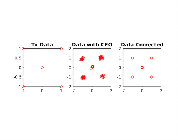
figure
subplot(131)
plot(real(inputiFFT), imag(inputiFFT),'rO');
axis square;
axis([-1 1 -1 1])
title('Tx Data','fontsize',12)
subplot(132)
plot(real(dataRaw), imag(dataRaw),'rO')
title('Data with CFO','fontsize',12)
axis square;
subplot(133)
plot(real(dataCFOCor), imag(dataCFOCor),'rO')
title('Data Corrected','fontsize',12)
axis square;